




Why Transformer Oil Filtration is Important? forumelectrical.com/oil-filt…
Transformer oil performs two essential functions: electrical insulation and heat dissipation. Over time, moisture, oxidation by-products, and suspended contaminants can degrade its insulating properties and affect transformer performance.
Key Benefits of Transformer Oil Filtration:
Improves the dielectric strength (BDV) of transformer oil.
Reduces moisture and particulate contamination.
Enhances electrical insulation reliability.
Helps prevent insulation-related failures.
Improves heat transfer and cooling performance.
Supports longer transformer service life.
Reduces the risk of unexpected outages and maintenance costs.
Practical Maintenance Result:
Oil filtration improved the measured Breakdown Voltage (BDV) from 45 kV to 65 kV, indicating an improvement in the dielectric strength of the processed oil under the specified test conditions.
Regular transformer oil testing, filtration, dehydration, and condition monitoring are essential preventive maintenance practices for reliable power system operation.
forumelectrical.com/oil-filt…
Follow Us On:
Website: forumelectrical.com
Facebook: facebook.com/profile.php?id=…
LinkedIn: linkedin.com/showcase/911302…
Twitter: teapaw.org/ForumEIectrical
Pinterest: ru.pinterest.com/ForumElectr…
WhatsApp Channel: whatsapp.com/channel/0029VbB…
Telegram: t.me/F0rumElectrical
#TransformerOilFiltration #TransformerOilTesting #BDVTest #BreakdownVoltage #TransformerMaintenance #TransformerOilDehydration #DielectricStrength #PowerTransformer #TransformerTesting #TransformerConditionMonitoring #ElectricalMaintenance #PreventiveMaintenance #PowerSystemReliability #SubstationMaintenance #ElectricalEngineering #PowerDistribution #AssetManagement #ElectricalSafety
forumelectrical.com/oil-filt…

1
69
Pre-Commissioning vs Commissioning forumelectrical.com/mdb-and-…
Understand the differences between pre-commissioning and commissioning activities in electrical installations, including inspection, insulation resistance testing, continuity checks, functional testing, protection relay testing, equipment verification, and operational performance checks.
forumelectrical.com/essentia…
Follow Us On:
Website: forumelectrical.com
Facebook: facebook.com/profile.php?id=…
LinkedIn: linkedin.com/showcase/911302…
Twitter: teapaw.org/ForumEIectrical
Pinterest: ru.pinterest.com/ForumElectr…
WhatsApp Channel: whatsapp.com/channel/0029VbB…
Telegram: t.me/F0rumElectrical
#PreCommissioning #Commissioning #ElectricalCommissioning #ElectricalTesting #ElectricalInspection #ElectricalMaintenance #InsulationResistanceTest #ContinuityTest #ProtectionRelayTesting #SwitchgearTesting #TransformerTesting #ElectricalInstallation #SubstationCommissioning #FAT #SAT #MCC #Switchboard #Switchgear #ElectricalEngineering #PowerSystems #ElectricalSafety
forumelectrical.com/mdb-and-…

Types of AC Motor Duty Cycles According to IEC Standards
forumelectrical.com/types-of…
Understand the different AC motor duty classifications from S1 to S10 as defined in IEC 60034-1. Learn about continuous duty, short-time duty, intermittent periodic duty, starting conditions, braking, and load variations for correct motor selection and industrial application.
Follow Us On:
Website: forumelectrical.com
Facebook: facebook.com/profile.php?id=…
LinkedIn: linkedin.com/showcase/911302…
Twitter: teapaw.org/ForumEIectrical
Pinterest: ru.pinterest.com/ForumElectr…
WhatsApp Channel: whatsapp.com/channel/0029VbB…
Telegram: t.me/F0rumElectrical
#ACMotor #MotorDutyCycle #IEС60034 #ElectricalEngineering #ElectricMotor #MotorSelection #MotorRating #ContinuousDuty #ShortTimeDuty #IntermittentDuty #S1Duty #S2Duty #S3Duty #S4Duty #S5Duty #S6Duty #S7Duty #S8Duty #S9Duty #S10Duty #IndustrialMotors #ElectricalMaintenance #MotorControl #PowerSystems #ElectricalDesign
forumelectrical.com/types-of…

Electrical Panel Factory Acceptance Test (FAT) – Testing and Inspection Procedure for LV Panels, MCC, Switchboards and Switchgear forumelectrical.com/fat-proc…
forumelectrical.com/fat-proc…
Follow Us On:
Website: forumelectrical.com
Facebook: facebook.com/profile.php?id=…
LinkedIn: linkedin.com/showcase/911302…
Twitter: teapaw.org/ForumEIectrical
Pinterest: ru.pinterest.com/ForumElectr…
WhatsApp Channel: whatsapp.com/channel/0029VbB…
Telegram: t.me/F0rumElectrical
#ElectricalPanelFAT #FactoryAcceptanceTest #FATProcedure #LVElectricalPanel #MotorControlCenter #MCCPanel #SwitchboardTesting #SwitchgearTesting #ElectricalPanelTesting #ElectricalInspection #ElectricalCommissioning #ElectricalTesting #ElectricalEngineering #IEC61439 #ElectricalMaintenance #PowerDistribution
forumelectrical.com/fat-proc…

Maintenance in Electrical Distribution Networks
forumelectrical.com/maintena…
Follow Us On:
Website: forumelectrical.com
Facebook: facebook.com/profile.php?id=…
LinkedIn: linkedin.com/showcase/911302…
Twitter: teapaw.org/ForumEIectrical
Pinterest: ru.pinterest.com/ForumElectr…
WhatsApp Channel: whatsapp.com/channel/0029VbB…
Telegram: t.me/F0rumElectrical
#ElectricalDistribution #ElectricalNetworkMaintenance #PowerDistribution #ElectricalMaintenance #DistributionSystem #PowerSystemEngineering #ElectricalEngineering #PreventiveMaintenance #PredictiveMaintenance #ElectricalSafety #DistributionTransformer #SubstationMaintenance #SwitchgearMaintenance #PowerGrid #ElectricalInfrastructure #ElectricalTesting #FaultDetection #PowerDistributionNetwork
forumelectrical.com/maintena…

Breaker Sizing Calculator forumelectrical.com/acb-size…
forumelectrical.com/acb-size…
Follow Us On:
Website: forumelectrical.com
Facebook: facebook.com/profile.php?id=…
LinkedIn: linkedin.com/showcase/911302…
Twitter: teapaw.org/ForumEIectrical
Pinterest: ru.pinterest.com/ForumElectr…
WhatsApp Channel: whatsapp.com/channel/0029VbB…
Telegram: t.me/F0rumElectrical
#BreakerSizingCalculator #ACBSizeCalculator #ACBSelection #AirCircuitBreaker #CircuitBreakerSizing #BreakerRating #ElectricalProtection #OvercurrentProtection #ShortCircuitProtection #ElectricalCalculations #ElectricalTools #ElectricalEngineering #Switchgear #PowerDistribution #ElectricalDesign #IndustrialElectrical #FaultCurrentCalculation #CircuitBreakerSelection
forumelectrical.com/acb-size…

Lightning Arrester Testing Procedure forumelectrical.com/lightnin…
Learn the essential testing procedures for lightning arresters (surge arresters) used in electrical substations and power distribution systems. Understand insulation resistance testing, leakage current measurement, reference voltage testing, and condition assessment to ensure reliable overvoltage protection and equipment safety.
forumelectrical.com/lightnin…
Follow Us On:
Website: forumelectrical.com
Facebook: facebook.com/profile.php?id=…
LinkedIn: linkedin.com/showcase/911302…
Twitter: teapaw.org/ForumEIectrical
Pinterest: ru.pinterest.com/ForumElectr…
WhatsApp Channel: whatsapp.com/channel/0029VbB…
Telegram: t.me/F0rumElectrical
#LightningArrester #SurgeArrester #LightningArresterTesting #SurgeArresterTesting #InsulationResistanceTest #LeakageCurrentTest #ReferenceVoltageTest #HighVoltageTesting #SubstationTesting #ElectricalTesting #ElectricalMaintenance #PowerSystemProtection #OvervoltageProtection #ElectricalEngineering #PowerDistribution #SubstationCommissioning #ForumElectrical
forumelectrical.com/lightnin…

Difference Between OTI and WTI in Power Transformers – Understand Their Functions, Working Principles & Applications! ⚡🌡️
🔗 forumelectrical.com/differen…
Topic: OTI vs WTI in Power Transformers – Oil Temperature Indicator and Winding Temperature Indicator
Temperature monitoring is essential for the safe and reliable operation of power transformers. The Oil Temperature Indicator (OTI) and Winding Temperature Indicator (WTI) are important protective and monitoring devices that help prevent transformer overheating, insulation deterioration, and unexpected failures.
But what is the difference between OTI and WTI? How do they work, and why are both important in transformer protection?
This technical guide explains:
✅ OTI (Oil Temperature Indicator): Function, working principle, and monitoring of transformer top-oil temperature.
✅ WTI (Winding Temperature Indicator): Function, working principle, and estimation of winding hot-spot temperature.
✅ Operating Principles: How temperature sensing systems and thermal simulation work.
✅ Alarm and Trip Functions: Temperature-based alarm and trip arrangements for transformer protection.
✅ OTI vs WTI: Key differences in measurement, applications, and protection functions.
✅ Transformer Protection: Importance of temperature monitoring in preventing overheating and extending transformer service life.
🎯 Who Should Read This Article?
Perfect for electrical engineers, transformer maintenance technicians, substation engineers, electrical supervisors, commissioning engineers, and students preparing for electrical engineering interviews.
📖 Read the Full Technical Guide Here:
forumelectrical.com/differen…
💡 Technical Discussion: Do you know why WTI generally indicates a higher temperature than OTI during transformer loading? Share your technical knowledge in the comments!
📌 Found this article helpful? Share it with fellow electrical engineers, transformer technicians, and maintenance professionals.
#OTI #WTI #OilTemperatureIndicator #WindingTemperatureIndicator #PowerTransformer #TransformerProtection #TransformerMaintenance #TransformerTesting #TransformerMonitoring #TransformerOverheating #TransformerTemperature #ElectricalEngineering #ElectricalMaintenance #SubstationEngineering #PowerSystemProtection #PowerSystems #ElectricalSafety #TransformerTechnician #ElectricalEngineer #ElectricalSupervisor #TestingAndCommissioning #PreventiveMaintenance #PowerDistribution #HighVoltageEngineering
forumelectrical.com/differen…

Why Do High-Voltage Transmission Lines Have No Neutral Wire? forumelectrical.com/category…
High-voltage three-phase transmission systems generally use three phase conductors (R, Y, B) without a separate neutral conductor.
In a balanced three-phase system, the three phase currents are displaced by 120 electrical degrees, and their instantaneous vector sum is zero. Therefore, the neutral conductor is not normally required for transmitting balanced three-phase power.
Key Technical Reasons:
Balanced three-phase loads do not require a neutral return conductor.
Electrical power is transmitted through three phase conductors.
Omitting a separate neutral conductor reduces transmission line infrastructure and associated costs.
The neutral point is generally established at suitable transformer winding connections in the power system.
Ground wires or shield wires installed above transmission conductors provide lightning protection; they are not neutral conductors.
#ElectricalTransmission #HighVoltageTransmission #ThreePhasePower #TransmissionLines #NeutralConductor #PowerSystemEngineering #ElectricalEngineering #ElectricalBasics #PowerDistribution #SubstationEngineering #ElectricalSafety #GridInfrastructure #PowerSystems
forumelectrical.com/category…

What could be the possible cause of this electrical fault? forumelectrical.com/common-e…
Identifying the root cause of electrical faults is essential for maintaining power system reliability, preventing equipment damage, and ensuring electrical safety.
#ElectricalFault #ElectricalTroubleshooting #ElectricalEngineering #Electrician #Lineman #PowerDistribution #ElectricalMaintenance #FaultDiagnosis #ElectricalSafety #PowerSystems #ElectricalTechnician #ElectricalWork #EngineeringReels #viralreels
forumelectrical.com/common-e…

Why does a Capacitor Store Electrical Energy in an Electric Field? forumelectrical.com/capacito…
A capacitor stores electrical energy in the electric field formed between two conductive plates separated by an insulating dielectric material.
When a DC voltage is applied, opposite electrical charges accumulate on the plates, creating an electric field across the dielectric. The energy is stored in this electric field rather than being stored as electrical current.
The stored energy depends on the capacitance and applied voltage.
Capacitor Energy Storage Formula:
E = 1/2 CV²
A capacitor stores energy through charge separation and the resulting electric field. When connected to a suitable circuit, the stored energy can be released to supply electrical power.
#CapacitorWorkingPrinciple #CapacitorEnergyStorage #ElectricField #Capacitance #ElectricalEngineering #ElectronicsEngineering #ElectricalFundamentals #EnergyStorage #DielectricMaterial #CapacitorTheory #ElectricalTheory #PowerElectronics #CircuitTheory
forumelectrical.com/capacito…

23
352
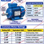
Why are Electric Motors Rated in HP or kW? forumelectrical.com/kw-to-hp…
Electric motors are rated in Horsepower (HP) or kilowatts (kW) because these units represent the mechanical output power delivered by the motor shaft.
The motor power rating indicates its ability to drive mechanical loads such as pumps, fans, compressors, conveyors, and industrial machinery.
Key Technical Points:
Kilowatt (kW): SI unit of power used to express the motor's rated mechanical output.
Horsepower (HP): Traditional unit of mechanical power commonly used in motor specifications.
1 HP: Approximately 0.746 kW.
1 kW: Approximately 1.341 HP.
Electrical Input Power: Higher than mechanical output power because of motor losses.
Motor Efficiency: Determines how effectively electrical input power is converted into mechanical output power.
Important: Motor HP or kW ratings generally indicate shaft output power, not electrical input power. Current consumption depends on supply voltage, power factor, and motor efficiency.
Technical Discussion: Why do you think motor manufacturers commonly specify output power instead of electrical input power on motor nameplates?
#ElectricMotor #MotorPowerRating #HPtoKW #KWtoHP #ElectricalEngineering #MotorEfficiency #ElectricMotorWorking #IndustrialMotors #MotorNameplate #ElectricalMachines #PowerEngineering #MechanicalPower #ElectricalBasics #IndustrialAutomation
forumelectrical.com/kw-to-hp…

Why Is Electrical Cable Size Selected Based on Current-Carrying Capacity? forumelectrical.com/power-li…
Electrical cable size is selected according to its current-carrying capacity (ampacity) to prevent excessive conductor heating, insulation damage, premature cable failure, and potential fire hazards.
When electrical current flows through a cable, heat is generated due to conductor resistance (I²R losses). Selecting the correct conductor cross-sectional area ensures that the cable can safely carry the design current without exceeding its permissible operating temperature.
Key Factors Affecting Cable Size Selection:
Load current and maximum demand.
Conductor material (Copper or Aluminium).
Cable insulation type and temperature rating.
Installation method and ambient temperature.
Cable grouping and derating factors.
Voltage drop limitations.
Short-circuit thermal withstand capacity.
Protective device rating and coordination.
Important Engineering Principle: The cable's corrected current-carrying capacity must be adequate for the design load and coordinated with the protective device to ensure effective overload and short-circuit protection.
Technical Discussion: Which factor has the greatest influence on cable sizing in your electrical projects: ampacity, voltage drop, short-circuit withstand, or installation conditions?
#CableSizing #CurrentCarryingCapacity #CableAmpacity #ElectricalEngineering #ElectricalDesign #ElectricalInstallation #CableSelection #VoltageDrop #ShortCircuitProtection #OverloadProtection #CopperCable #AluminiumCable #PowerDistribution #ElectricalSafety #ElectricalStandards
forumelectrical.com/power-li…

Arc Flash Hazards and Electrical Safety forumelectrical.com/why-stan…
An arc flash is a serious electrical hazard that can release enormous thermal energy, intense light, pressure waves, and molten metal within milliseconds.
The consequences can include severe burns, hearing damage, eye injuries, blast-related trauma, and life-threatening injuries.
Unlike electrical shock, arc flash incidents can cause extensive injuries through:
Extreme thermal energy and heat exposure.
Arc blast pressure and flying debris.
Intense light and ultraviolet radiation.
Loud noise and hearing damage.
Molten metal and equipment fragmentation.
Essential Arc Flash Safety Measures
Conduct an arc flash risk assessment.
Perform incident energy calculations.
Establish arc flash boundaries.
Display appropriate arc flash warning labels.
Select arc-rated PPE based on calculated incident energy.
Follow electrical isolation and Lockout/Tagout (LOTO) procedures.
Apply appropriate safe work practices and electrical protection measures.
Important Technical Note: Never assume that standard electrical PPE provides arc flash protection. PPE selection must be based on the applicable risk assessment and incident energy analysis.
An arc flash hazard must be identified and controlled before electrical work begins. Prevention, engineering controls, safe isolation, and appropriate PPE are essential for protecting electrical personnel.
#ArcFlash #ArcFlashSafety #ElectricalSafety #ArcFlashHazard #IncidentEnergy #ArcFlashBoundary #ArcRatedPPE #ElectricalEngineering #ElectricalMaintenance #LOTO #ElectricalRiskAssessment #PowerSystems #WorkplaceSafety #NFPA70E #ElectricalProtection
forumelectrical.com/why-stan…

33/11 kV Substation Single Line Diagram (SLD) – Main Components and Working Principle forumelectrical.com/33kv-11k…
A 33/11 kV distribution substation receives electrical power at 33 kV, steps down the voltage to 11 kV through a power transformer, and distributes it to downstream distribution feeders. The substation incorporates switching, protection, metering, and isolation equipment to ensure reliable power distribution.
1. 33 kV Incoming Section (High-Voltage Side)
•Lightning Arrester (LA): Protects substation equipment against transient overvoltages caused by lightning and switching surges.
•Isolator (Disconnector): Provides visible electrical isolation for maintenance. It is operated under no-load conditions unless specifically rated for switching duties.
•Current Transformer (CT): Steps down primary current for protection relays and metering instruments.
•Potential Transformer (PT): Provides a reduced voltage signal for metering, monitoring, and protection.
•Vacuum Circuit Breaker (VCB): Performs normal switching and interrupts fault currents within its rated breaking capacity.
•33 kV Busbar: Collects and distributes incoming electrical power to the transformer bay and associated circuits.
2. 33/11 kV Power Transformer
•Steps down the incoming voltage from 33 kV to 11 kV.
•Transfers electrical power through electromagnetic induction.
•May incorporate a Buchholz relay for detecting internal faults in oil-filled conservator-type transformers.
•Includes cooling arrangements, temperature monitoring, and protective devices according to its design.
3. 11 kV Outgoing Distribution Section (Low-Voltage Side)
•11 kV Busbar: Receives power from the transformer secondary and distributes it to outgoing feeders.
•11 kV VCBs: Provide switching and fault interruption for individual feeder circuits.
•CTs and Protection Relays: Monitor feeder current and initiate circuit breaker tripping during detected faults.
•Isolators: Provide electrical isolation for maintenance.
•Outgoing 11 kV Feeders: Supply distribution transformers, industrial installations, and downstream electrical loads.
Engineering Note: The actual single-line diagram and equipment sequence depend on the substation configuration, protection philosophy, busbar arrangement, utility requirements, and applicable IEC standards.
#33kVSubstation #11kVSubstation #3311kVSubstation #SubstationSLD #SingleLineDiagram #PowerTransformer #VacuumCircuitBreaker #VCB #CurrentTransformer #PotentialTransformer #LightningArrester #BusbarProtection #ElectricalProtection #PowerDistribution #SubstationEngineering #ElectricalEngineering #HighVoltageEngineering
forumelectrical.com/33kv-11k…

What is power factor? forumelectrical.com/power-fa…
Power factor (PF) is the ratio of active power (kW) to apparent power (kVA). It indicates how effectively electrical power is converted into useful work in an electrical system.
1. Displacement Power Factor
Displacement power factor is the cosine of the phase angle (φ) between the fundamental-frequency voltage and current waveforms. It is applicable to sinusoidal conditions and represents the phase displacement between voltage and current.
Displacement PF = cos φ
2. Distortion Power Factor
Distortion power factor represents the effect of current harmonics produced by nonlinear loads such as VFDs, UPS systems, rectifiers, and electronic equipment.
For sinusoidal supply voltage:
Distortion PF = 1 / √(1 + THDi²)
Where THDi is the total harmonic distortion of current, expressed as a per-unit value.
3. True Power Factor
True power factor accounts for both phase displacement and waveform distortion.
True PF = Displacement PF × Distortion PF
Engineering Note: Power factor improvement using capacitor banks primarily corrects displacement power factor. Harmonic distortion may require additional solutions, such as detuned capacitor banks or harmonic filters, depending on the system conditions.
Understanding displacement power factor, distortion power factor, and total harmonic distortion is essential for electrical system analysis, power quality assessment, and energy efficiency.
#PowerFactor #DisplacementPowerFactor #DistortionPowerFactor #TruePowerFactor #PowerFactorCorrection #Harmonics #THDi #PowerQuality #ElectricalEngineering #PowerSystems #ElectricalDesign #HarmonicAnalysis #CapacitorBank #ETAP #IndustrialElectrical
forumelectrical.com/power-fa…

What is Load Flow Analysis in Power Systems? forumelectrical.com/differen…
Load Flow Analysis also known as Power Flow Analysis, is an essential power system study used to determine the steady-state operating conditions of an electrical network.
It calculates the following parameters based on the network configuration, load demand, generator operating conditions, and system parameters:
•Voltage magnitude and phase angle at each busbar.
•Active power (MW) and reactive power (MVAr) flow through transmission lines and transformers.
•Real and reactive power losses in the electrical network.
•Generator power output and bus voltage profiles.
•Power system loading and operating conditions.
Load flow studies are widely used in power system planning, transmission network analysis, substation design, voltage regulation, and electrical system optimization using software such as ETAP, PSS/E, and DIgSILENT PowerFactory.
Common Load Flow Calculation Methods: Gauss-Seidel, Newton-Raphson, and Fast Decoupled Load Flow.
#LoadFlowAnalysis #PowerFlowAnalysis #PowerSystemAnalysis #ElectricalEngineering #ETAP #PowerSystems #NewtonRaphson #GaussSeidel #TransmissionLines #SubstationEngineering #VoltageStability #ReactivePower #ActivePower #PowerSystemStudies #ElectricalDesign
forumelectrical.com/differen…

EARTHING RESISTANCE TESTING – 3-POLE METHOD forumelectrical.com/method-s…
Earth resistance testing using the 3-pole method is performed to measure the resistance of an earthing electrode or grounding system with respect to remote earth. The test is conducted using a Digital Earth Resistance Tester and three terminals: E (Earth electrode under test), P (Potential spike), and C (Current spike).
The auxiliary current spike is installed at a suitable distance from the electrode under test, while the potential spike is positioned between them. The 62% rule is commonly used to determine the potential spike position under suitable soil and electrode conditions. Multiple readings at different potential probe positions help verify measurement accuracy.
The measured earth resistance is evaluated to assess grounding system performance, electrical safety, and compliance with applicable project specifications and standards.
#EarthResistanceTesting #3PoleMethod #FallOfPotentialMethod #EarthingSystem #GroundingSystem #EarthElectrodeTesting #ElectricalTesting #SubstationCommissioning #EarthTester #ElectricalMaintenance #PowerSystemEngineering #ElectricalEngineering
forumelectrical.com/method-s…

kW to MCB Ampere Rating Calculation forumelectrical.com/kva-kw-a…
Understanding the relationship between electrical load (kW) and Miniature Circuit Breaker (MCB) current rating is essential for safe and reliable electrical installation design.
MCB current rating selection depends on:
Connected load (kW)
Supply voltage (V)
Single-phase or three-phase supply
Power factor (PF)
Load efficiency, where applicable
Cable current-carrying capacity
Load characteristics and starting current
Important Technical Note: MCB selection must consider design current, cable ampacity, overload and short-circuit protection, fault level, and applicable electrical standards. A simple kW-to-ampere conversion is not sufficient for final MCB selection.
Technical Discussion: Which method do you prefer for MCB sizing in residential and industrial electrical installations: load-current calculation, cable-based selection, or protection coordination?
#KWtoMCB #MCBRatingCalculation #MCBSelection #ElectricalLoadCalculation #CircuitBreakerSelection #ElectricalEngineering #ElectricalSafety #PowerSystems #ElectricalDesign #OvercurrentProtection #CableSizing #SinglePhase #ThreePhase #ElectricalInstallation #ElectricianTraining
forumelectrical.com/kva-kw-a…

Voltage Drop Calculation forumelectrical.com/voltage-…
Three-Phase Voltage Drop Calculation for 600 kW Load – 415V Aluminium Cable Sizing Example
Voltage drop calculation is essential in electrical power distribution system design to maintain voltage regulation, improve power quality, and ensure reliable equipment operation.
Practical Engineering Example
Project Parameters:
Connected Load: 600 kW
System Voltage: 415 V, Three-Phase
Power Factor: 0.9
Cable Length: 25 m
Cable Specification: 3.5C × 300 mm² Aluminium XLPE
Combined Impedance Term: 0.1455 Ω/km
1. Load Current Calculation
Formula:
I = P / (√3 × V × PF)
Calculated Load Current = 927.5 A
2. Cable Length Conversion
25 m = 0.025 km
3. Voltage Drop Calculation
VD = √3 × I × L × (R cosφ + X sinφ)
Calculated Voltage Drop = 5.84 V
4. Percentage Voltage Drop
%VD = (5.84 / 415) × 100
Calculated Voltage Drop = 1.41%
Engineering Considerations
The calculated voltage drop of 1.41% is within the commonly adopted 5% design criterion. However, final cable selection must also consider:
Cable current-carrying capacity and parallel cable requirements.
Installation method and ambient temperature.
Cable grouping and derating factors.
Short-circuit thermal withstand capacity.
Protective device coordination and voltage regulation.
Important Technical Note: A voltage drop calculation alone cannot confirm cable suitability. The 927.5 A load current requires verification of the cable ampacity, installation conditions, and number of parallel cable runs. The assumed impedance value and calculation method must also be verified against the manufacturer's cable data.
Technical Discussion: Which factor creates the biggest challenge in electrical cable sizing: voltage drop, current-carrying capacity, short-circuit withstand, or installation constraints?
#VoltageDropCalculation #CableSizing #ElectricalDesign #ThreePhasePower #PowerDistribution #AluminiumCable #XLPECable #ElectricalEngineering #LoadCurrentCalculation #VoltageRegulation #ElectricalCalculations #PowerSystems #CableAmpacity #ShortCircuitCalculation #ElectricalSafety
forumelectrical.com/voltage-…
